All-Terrain
Prosthetic
Ankle-Foot

Siemens NX FEA / Structural Analysis PETG & Photopolymer Resin 3D Printing Biomechanical Design

Designed and validated a fully mechanical, dual-axis ankle-foot prosthesis to improve stability and adaptability during walking on uneven terrain — without any electronics.

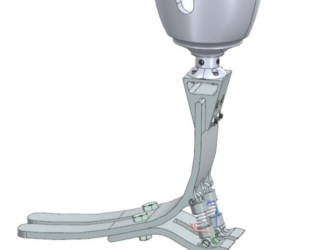
Full Prosthetic Ankle-Foot Assembly
2
Degrees of freedom (dorsiflexion & eversion)
FEA
Full structural validation under physiological loads
0
Electronics — fully passive mechanical system
Physical prototype built and tested

Project Overview

This project focused on designing and validating a fully mechanical, dual-axis ankle-foot prosthesis to improve stability and adaptability during walking on uneven terrain. The system provides natural ankle motion without electronics, prioritizing reliability, manufacturability, and cost-effectiveness.

The design centers on passive mechanical compliance to accommodate real-world terrain variations while maintaining structural integrity under repeated physiological loading. All components were developed with rapid prototyping and scalability in mind.
Engineering Objectives

  • Enable controlled dorsiflexion and plantarflexion during gait
  • Accommodate inversion and eversion caused by uneven terrain
  • Ensure structural safety under cyclic body-weight loading
  • Design for ease of manufacturing and assembly
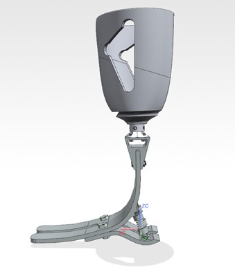
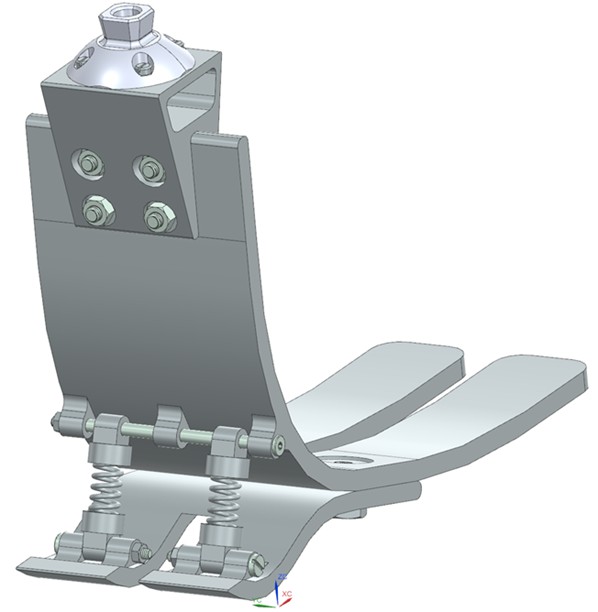
CAD Assembly

Mechanical Detail

My Technical Contributions

  • Developed parametric CAD models and full mechanical assemblies in Siemens NX
  • Defined load paths, joint interfaces, and component constraints
  • Selected materials based on strength, stiffness, and manufacturability
  • Prepared engineering documentation and design rationale

Key Design Decisions

  • Dual-degree-of-freedom architecture for realistic ankle motion
  • Spring-based restoring mechanisms to maintain neutral alignment
  • Modular design enabling rapid iteration and testing

Engineering Analysis & Validation

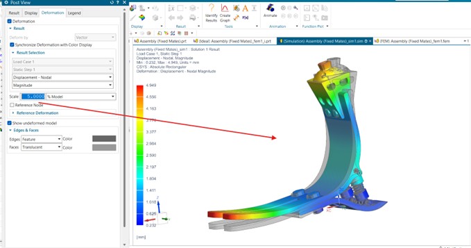
Finite Element Analysis (FEA) was conducted to assess the structural performance of critical load-bearing components under representative walking loads.
Analysis Setup

  • Applied vertical and angled loads simulating stance-phase loading
  • Boundary conditions defined at pylon and ground-contact interfaces
  • Material models for PETG and rigid photopolymer resin

Results

  • Critical components showed stress levels within safe material limits
  • Identified high-stress regions and refined geometry to reduce stress concentrations
  • Confirmed design validity prior to physical prototyping
FEA Results

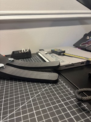
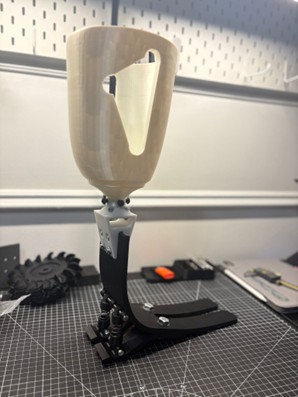
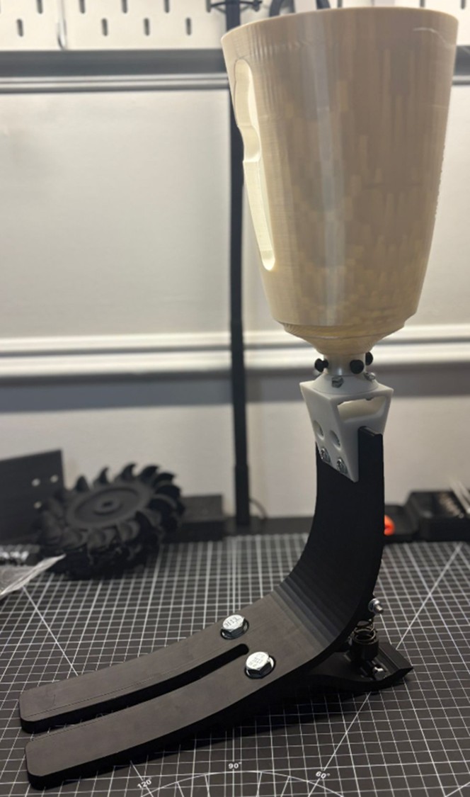
Physical Prototype

Prototyping & Testing

Physical prototypes were produced using FDM 3D printing in PETG and rigid photopolymer resin, enabling rapid validation of fit, function, and mechanical behavior.
Prototype Activities

  • Assembled and evaluated full prototype for joint range of motion
  • Tested spring-return mechanisms for consistency and alignment
  • Compared prototype behavior against CAD simulation predictions
  • Iterated on component geometry based on physical test observations